Explain How a Potentiometer Is Different From a Fixed Resistor
Observe how capacitor C3 decouples resistor R3 Q2s emitter load such that the Q2 emitter voltage follows the average collector voltage of Q1. Digital potentiometer ICsoften called digipotssolve these issues by bridging the digital domain and the analog resistor world.

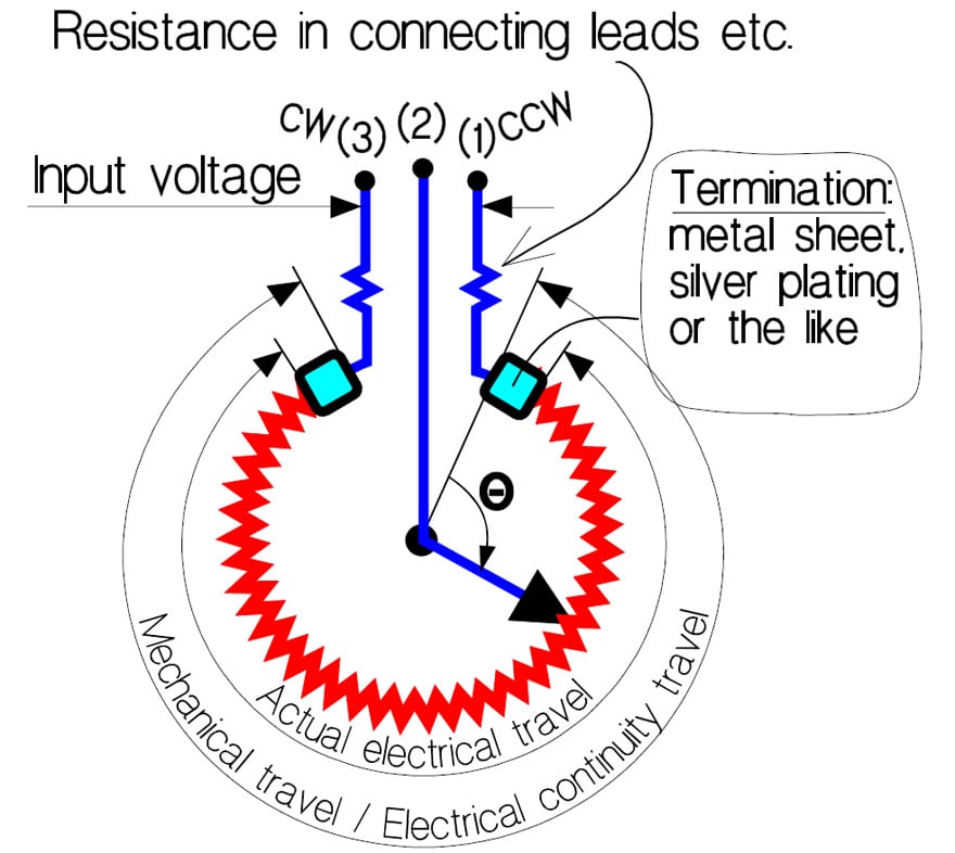
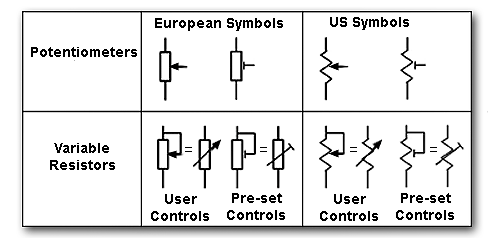
Potentiometers Basic Principles
How relays work.

. 2 Control the amplifier Gain. A resistor network is especially handy when building an audio mixer for example because each input typically has both a potentiometer to adjust level and a fixed resistor for isolation or to set a maximum input I. 1volume controls on audio equipment.
Keep in mind that the output is straight from the IC without the additional circuitry that I will continue to explain below. Digital Potentiometer MCP41100 and Arduino. The output of the IC is fed into the non-inverting input of the op-amp using a 13kΩ resistor.
On the Telecaster they are combined into one. We know the analog potentiometer is a three-terminal resistor with a sliding contact that forms an adjustable voltage divider. The value of the resistor should be roughly equal to the resistance of your thermistor.
How to Make a Bench Power Supply. In this tutorial we will be using an Arduino to control the speed and direction of a DC Motor. Negative DC feedback stabilizes the bias in this setup.
Tremolo bridges the sort that has a whammy bar found on guitars like the Stratocaster. Here are two simple animations illustrating how relays use one circuit to switch on a second circuit. For this tutorial we will be using our basic DC Hobby Motor but this tutorial can be applied to just about any DC Motor out there that falls within the peak voltage and current specifications of the H-Bridge we are using.
Using R2 the base bias for Q1 is obtained from the emitter of Q2. Potentiometers Many application such like. The bridge and tailpiece are mostly separate units but in some cases eg.
As an all-electronic microcontroller-compatible component digipots allow a processor and software to control set and vary their resistance value or voltage divider ratio. The manufacturer of the thermistor might tell you its resistance but if not you can use a multimeter to find out. A bench power supply is an extremely handy bit of kit to have around for electronics hobbyists but they can be expensive when purchased from the market.
In this case the resistance of my thermistor is 100K Ohms so my resistor is also 100K Ohms. Typically the resistor networks are a package of resistors where one end of each resistor is connected to a common lead and the other ends are all separate. In this Instructable I will show you how to make a.
The loudness of the circuit is controlled by the input potentiometer R4. We will be using ADC0 for our potentiometer input but you could also use one of the other two. Ratiometric Specified Functioning.
In our test we will use a potentiometer to present a variable voltage at the analog input which we will then read. When power flows through the first circuit 1 it activates the electromagnet brown generating a magnetic field blue that attracts a contact red and activates the second circuit 2. Note that while I show pin 23 as being the ground that was just for convenience you can use any Pico ground pin.
The tailpiece is what the strings attach to. Fixed or hard-tail bridges like you find on the Fender Telecaster.

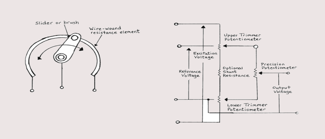
Electricity The Inside Of A Variable Resistor Potentiometer Physics Stack Exchange

Basic Principles Of Potentiometers Variable Resistors Doeeet Com
0 Response to "Explain How a Potentiometer Is Different From a Fixed Resistor"
Post a Comment